General Drawings
General drawings consist of plans (views from above) and elevations (side or front views) drawn on a relatively small scale. Both types of drawings use a standard set of architectural symbols. The most common construction plans are site plans, plot plans, foundation plans, floor plans, and framing plans. We will discuss each of them in the following paragraphs.
Site Plan
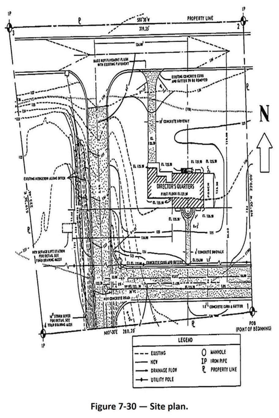
The site plan shown in Figure 7-30 shows the contours, boundaries, roads, utilities, trees, structures, and any other significant physical features on or near the construction site. It shows the locations of proposed structures in outline. This plan also shows corner locations relative to reference lines, shown on the plot, which can be located at the site. By showing both existing and finished contours, the site plan furnishes essential data for the graders and excavators.
General drawings consist of plans (views from above) and elevations (side or front views) drawn on a relatively small scale. Both types of drawings use a standard set of architectural symbols. The most common construction plans are site plans, plot plans, foundation plans, floor plans, and framing plans. We will discuss each of them in the following paragraphs.
Site Plan
The site plan shown in Figure 7-30 shows the contours, boundaries, roads, utilities, trees, structures, and any other significant physical features on or near the construction site. It shows the locations of proposed structures in outline. This plan also shows corner locations relative to reference lines, shown on the plot, which can be located at the site. By showing both existing and finished contours, the site plan furnishes essential data for the graders and excavators.
Plot Plans
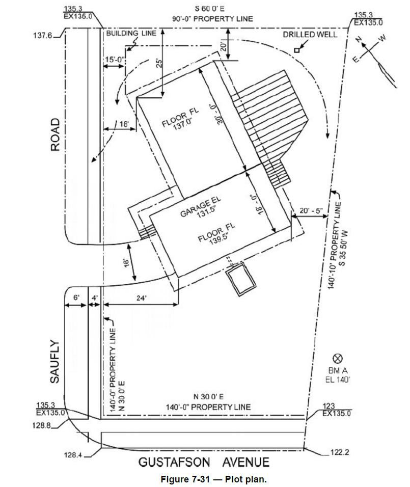
The plot plan shows the survey marks, including the bench mark (BM), with the elevations and the grading requirements. Surveyors use the plot plan shown in Figure 7-31 to set up the corners and perimeter of the building using batter boards and line stakes. The plot plan furnishes the essential data for laying out the building.
The plot plan shows the survey marks, including the bench mark (BM), with the elevations and the grading requirements. Surveyors use the plot plan shown in Figure 7-31 to set up the corners and perimeter of the building using batter boards and line stakes. The plot plan furnishes the essential data for laying out the building.
Foundation Plan
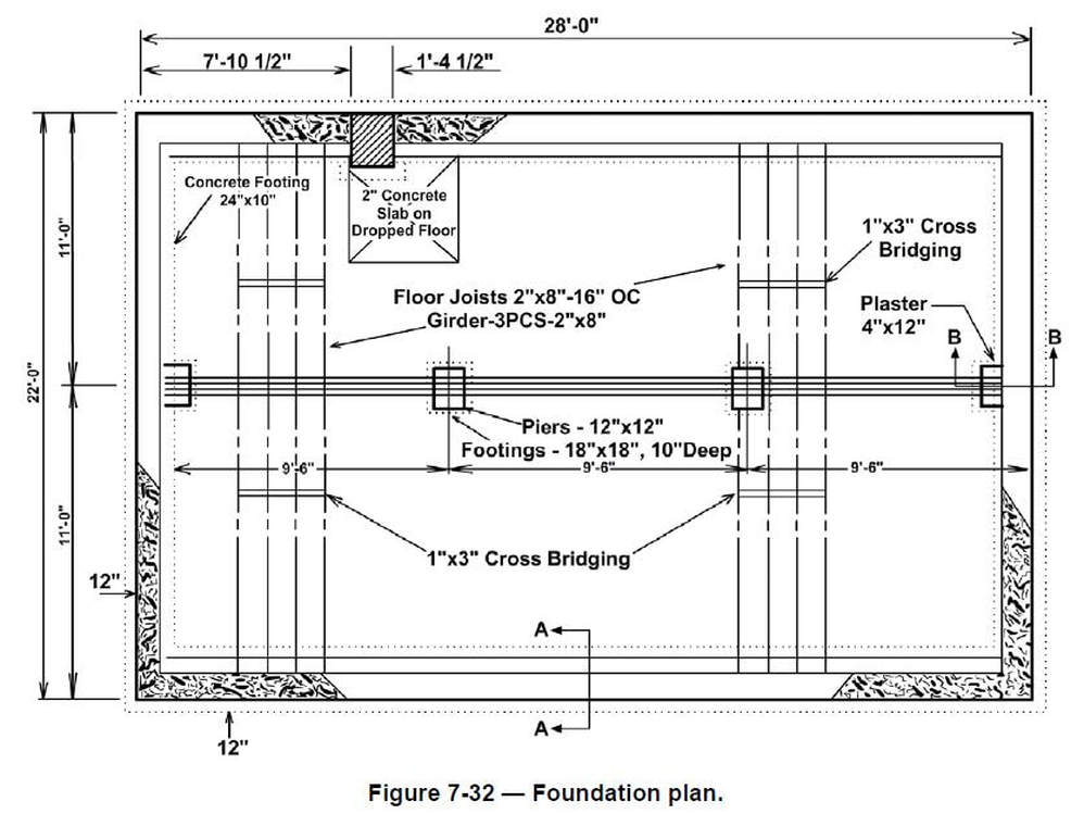
A foundation plan is a plane view of a structure. That is, it looks as if it were projected onto a horizontal plane and passed through the structure. In the case of the foundation plan, the plane is slightly below the level of the top of the foundation wall. The plan in Figure 7-32 shows that the main foundation consists of 12 inch and 8 inch concrete masonry unit (CMU) walls measuring 28 feet lengthwise and 22 feet crosswise. The lower portion of each lengthwise section of wall is to be 12 inches thick to provide a concrete ledge 4 inches wide.
A girder running through the center of the building will be supported at the ends by two 4 by 12 inch concrete pilasters butting against the end foundation walls. Intermediate support for the girder will be provided by two 12 by 12 inch concrete piers, each supported on 18 by 18 inch spread footings, which are 10 inches deep. The dotted lines around the foundation walls indicate that these walls will also rest on spread footings.
Floor Plan
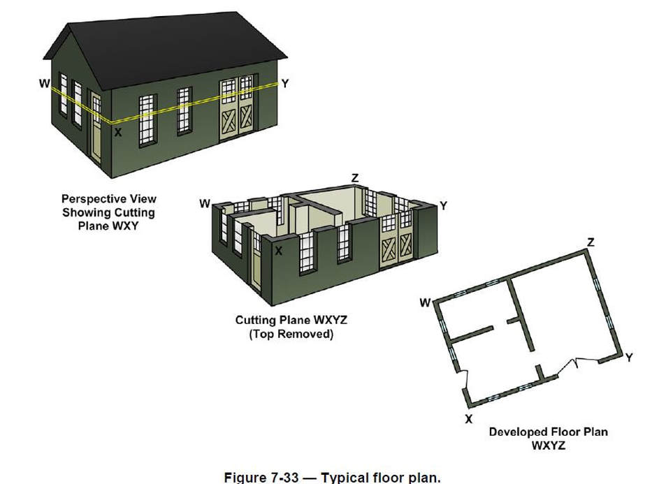
Floor plans are views of a building as though cutting planes were made through the building horizontally. The cutting plane is generally taken 5 feet 0 inches above the floor being shown.
The way a floor plan is developed from elevation, to cutting plane, to floor plan is depicted in Figure 7-33. An architectural or structural floor plan shows the structural characteristics of the building at the level of the plane of projection. A mechanical floor plan shows the plumbing and heating systems and any other mechanical components other than those that are electrical. An electrical floor plan shows the lighting systems and any other electrical systems.
Framing Plan
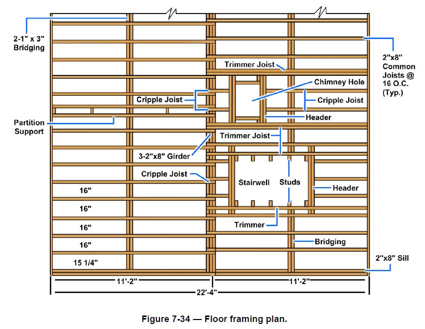
The floor framing plan (Figure 7-34) is a plan view of the layout of girders, beams, and joists. Joists and double framing are drawn in the position they will occupy in the completed building. Joists do not need dimensions at every location. Notes provide the necessary information, in this case “2" by 8" joists at 16 inches on center (O.C.).
Bridging is also drawn in position perpendicular to the joist but called out by note as “2- 1” x 3” bridging”. The span of the joist controls the number of required rows of cross bridging. The rows should not be more than 7 or 8 feet apart. Hence, a 14 foot span may need only one row of bridging, but a 16 foot span needs two rows. Notes also identify floor openings, trimmers, plates, or doubles to support heavier floor loads.
Floor framing plans do not indicate length dimensions for individual pieces. The builder is able to determine those from overall building dimensions, dimensions for each bay, or distances between columns or posts.
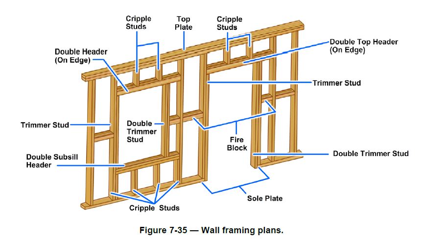
Wall framing plans (Figure 7-35) show the location and method of framing openings and ceiling heights so that studs and posts can be cut. Since it is a view on a vertical plane, a wall framing plan is not a plan in the strict technical sense. However, the practice of calling it a plan has become a general custom.
The floor framing plan (Figure 7-34) is a plan view of the layout of girders, beams, and joists. Joists and double framing are drawn in the position they will occupy in the completed building. Joists do not need dimensions at every location. Notes provide the necessary information, in this case “2" by 8" joists at 16 inches on center (O.C.).
Bridging is also drawn in position perpendicular to the joist but called out by note as “2- 1” x 3” bridging”. The span of the joist controls the number of required rows of cross bridging. The rows should not be more than 7 or 8 feet apart. Hence, a 14 foot span may need only one row of bridging, but a 16 foot span needs two rows. Notes also identify floor openings, trimmers, plates, or doubles to support heavier floor loads.
Floor framing plans do not indicate length dimensions for individual pieces. The builder is able to determine those from overall building dimensions, dimensions for each bay, or distances between columns or posts.
Wall framing plans (Figure 7-35) show the location and method of framing openings and ceiling heights so that studs and posts can be cut. Since it is a view on a vertical plane, a wall framing plan is not a plan in the strict technical sense. However, the practice of calling it a plan has become a general custom.
Roof framing plans for wood frame construction are drawn in the same manner as the floor framing plan. The rafters are shown in the same manner as joists, with rafters shown spanning the building and supporting the roof.
A utility plan is a floor plan that shows the layout of heating, electrical, plumbing, or other utility systems. Utility plans are used primarily by the ratings responsible for the utilities, and are equally important to the builder. Most utility installations require that openings be left in walls, floors, and roofs for the admission or installation of utility features. The builder who is placing a concrete foundation wall must study the utility plans to determine the number, sizes, and locations of openings he or she must leave for utilities.
A utility plan is a floor plan that shows the layout of heating, electrical, plumbing, or other utility systems. Utility plans are used primarily by the ratings responsible for the utilities, and are equally important to the builder. Most utility installations require that openings be left in walls, floors, and roofs for the admission or installation of utility features. The builder who is placing a concrete foundation wall must study the utility plans to determine the number, sizes, and locations of openings he or she must leave for utilities.
Elevations
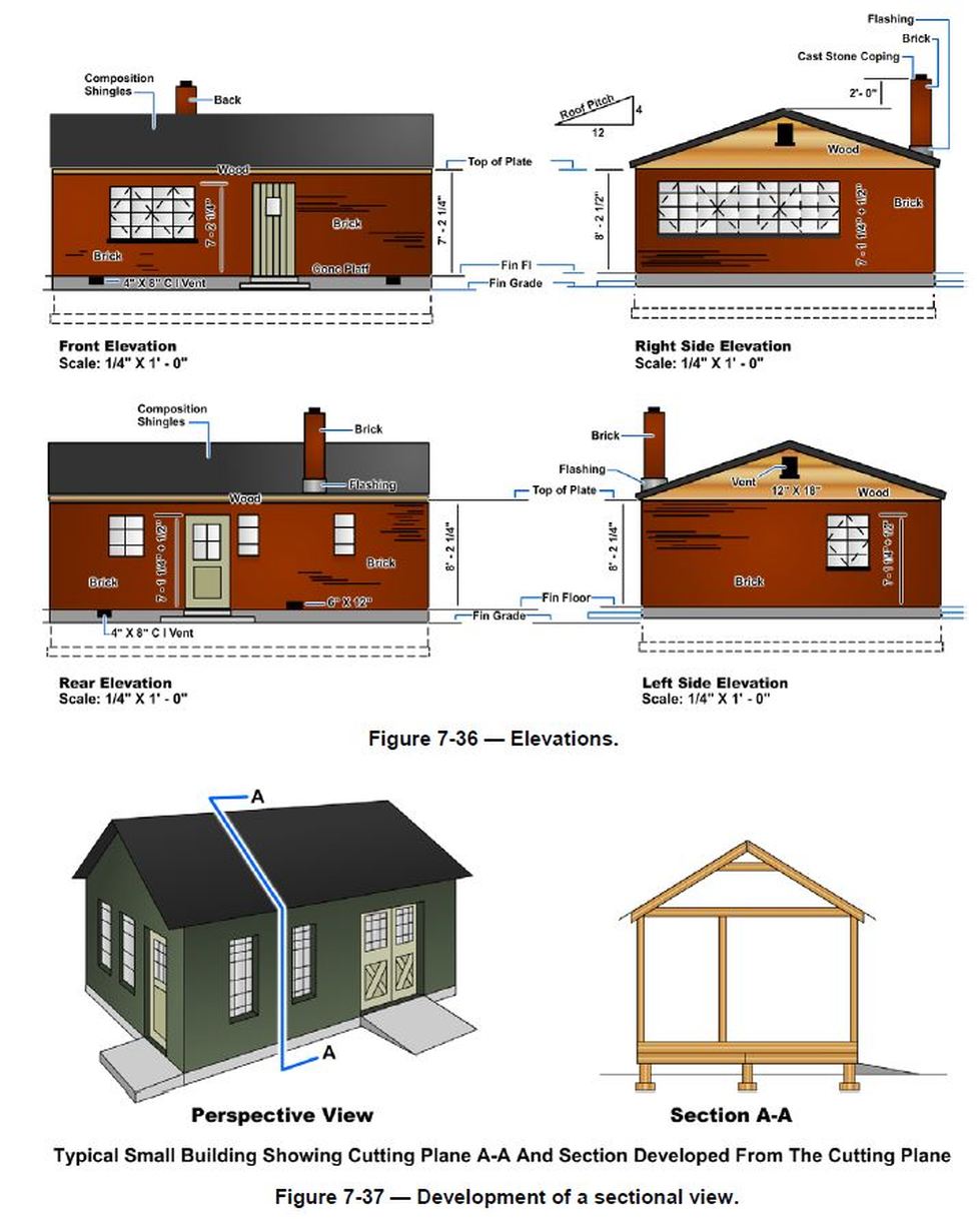
Elevations show the front, rear, and sides of a structure, as they would appear projected on vertical planes. Studying the elevation drawing (Figure 7-36) gives you a working idea of the appearance and layout of the structure.
Notice that the wall surfaces of this house will consist of brick and the roof covering of composition shingles. The top of the rafter plate will be 8 feet 2 1/4 inches above the level of the finished first floor, and the tops of the finished door and window openings 7 feet 1 3/4 inches above the same level. The roof will be a gable roof with 4 inches of rise for every 12 inches length. Each window shown in the elevations is identified by a capital letter that goes with a window schedule.
Detail Drawings
Sectional Views
Sectional views, or sections, provide important information about the height, materials, fastening and support systems, and concealed features of a structure. The initial development of a section and how a structure looks when cut vertically by a cutting plane is shown Figure 7-37. The cutting plane is not necessarily continuous, but, as with the horizontal cutting plane in building plans, may be staggered to include as much construction information as possible. Like elevations, sectional views are vertical projections. They are also detail drawings drawn to large scale. This aids in reading, and provides information that cannot be given on elevation or plan views. Sections are classified as typical and specific.
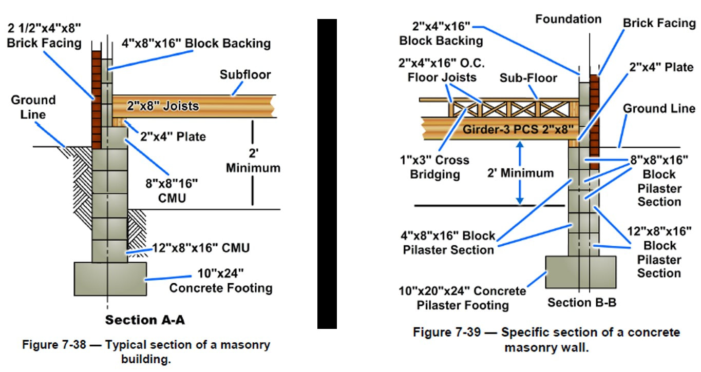
Typical sections (Figure 7-38) represent the average condition throughout a structure and are used when construction features are repeated many times. You can see that it gives a great deal of information necessary for those constructing the building.
The foundation plan shown in Figure 7-32 specifies that the main foundation of this structure will consist of a 22 by 28 foot concrete block rectangle. In Figure 7-38, the section A-A of the foundation plan shows that the front and rear portions of the foundation (28 foot measurements) are made of 12 by 8 by 16 inch CMUs centered on a 10 by 24 inch concrete footing to an unspecified height. These are followed by 8 inch CMUs, which form a 4 inch ledger for floor joist support on top of the 12 inch units. In this arrangement, the 8 inch CMUs serve to form a 4 inch support for the brick. The main wall is then laid with standard 2 1/2 by 4 by 8 inch face brick backed by 4 by 8 by 16 inch CMUs.
Section B-B, shown in Figure 7-39 of the foundation plan, shows that both side walls (22 foot measurements) are 8 inches thick centered on a 24 inch concrete footing to an unspecified height. It also illustrates the pilaster, a specific section of the wall to be constructed for support of the girder. It shows that the pilaster is constructed of 12 by 8 by 16 inch CMUs alternated with 4 by 8 by 16 inch and 8 by 8 by 16 inch CMUs. The hidden lines (dashed lines) on the 12 inch wide units indicate that the thickness of the wall beyond the pilaster is 8 inches. Notice how the extra 4 inch thickness of the pilaster provides a center support for the girder, which will support the floor joists.
Detail Views
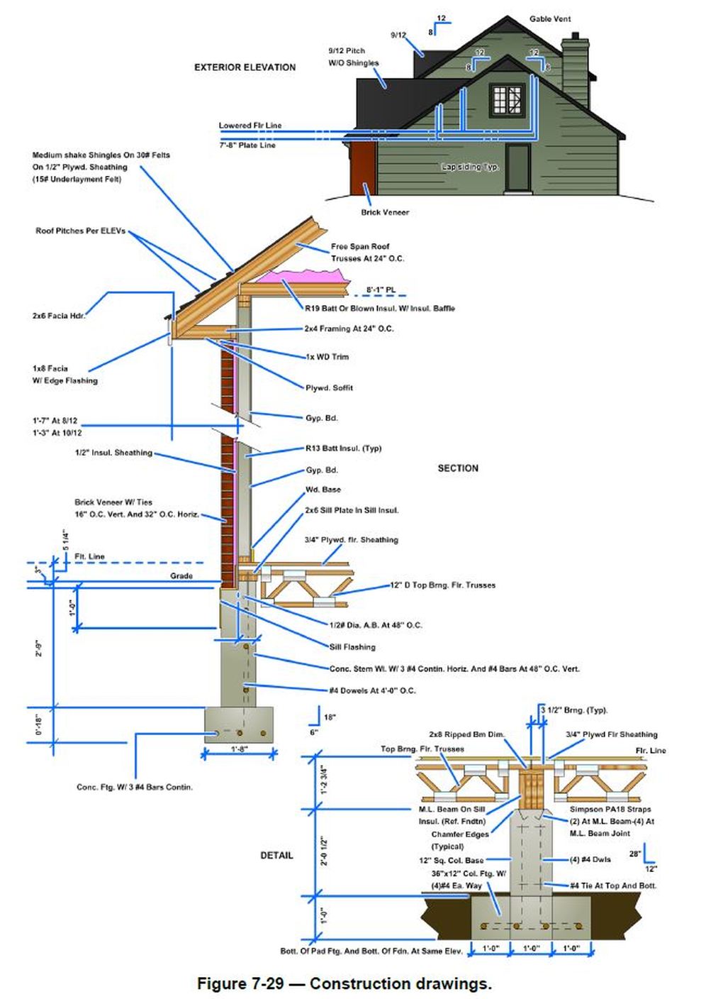
Detail views are large-scale drawings of construction assemblies and installations that cannot be clearly shown in the sections. These enlarged drawings show the various parts in more detail and how they will be connected and placed.
The foundation plan shown in Figure 7-32 specifies that the main foundation of this structure will consist of a 22 by 28 foot concrete block rectangle. In Figure 7-38, the section A-A of the foundation plan shows that the front and rear portions of the foundation (28 foot measurements) are made of 12 by 8 by 16 inch CMUs centered on a 10 by 24 inch concrete footing to an unspecified height. These are followed by 8 inch CMUs, which form a 4 inch ledger for floor joist support on top of the 12 inch units. In this arrangement, the 8 inch CMUs serve to form a 4 inch support for the brick. The main wall is then laid with standard 2 1/2 by 4 by 8 inch face brick backed by 4 by 8 by 16 inch CMUs.
Section B-B, shown in Figure 7-39 of the foundation plan, shows that both side walls (22 foot measurements) are 8 inches thick centered on a 24 inch concrete footing to an unspecified height. It also illustrates the pilaster, a specific section of the wall to be constructed for support of the girder. It shows that the pilaster is constructed of 12 by 8 by 16 inch CMUs alternated with 4 by 8 by 16 inch and 8 by 8 by 16 inch CMUs. The hidden lines (dashed lines) on the 12 inch wide units indicate that the thickness of the wall beyond the pilaster is 8 inches. Notice how the extra 4 inch thickness of the pilaster provides a center support for the girder, which will support the floor joists.
Detail Views
Detail views are large-scale drawings of construction assemblies and installations that cannot be clearly shown in the sections. These enlarged drawings show the various parts in more detail and how they will be connected and placed.
The scale depends on how large the drawing needs to be magnified to explain the required information clearly. Details are usually drawn at a larger scale than the sections, generally 1-, 1 1/2-, or 3-inch = 1 foot.
Architectural drawing standards contain details commonly used for installation of items such as door-frames, window frames, fireproofing, and material connections; they do, however, need to be adapted to the particular building being drawn. When different conditions actually exist, avoid the use of “typical” details; they will be misleading and cause confusion. The designer needs to understand construction well enough to make accurate detail drawings for each unique situation.
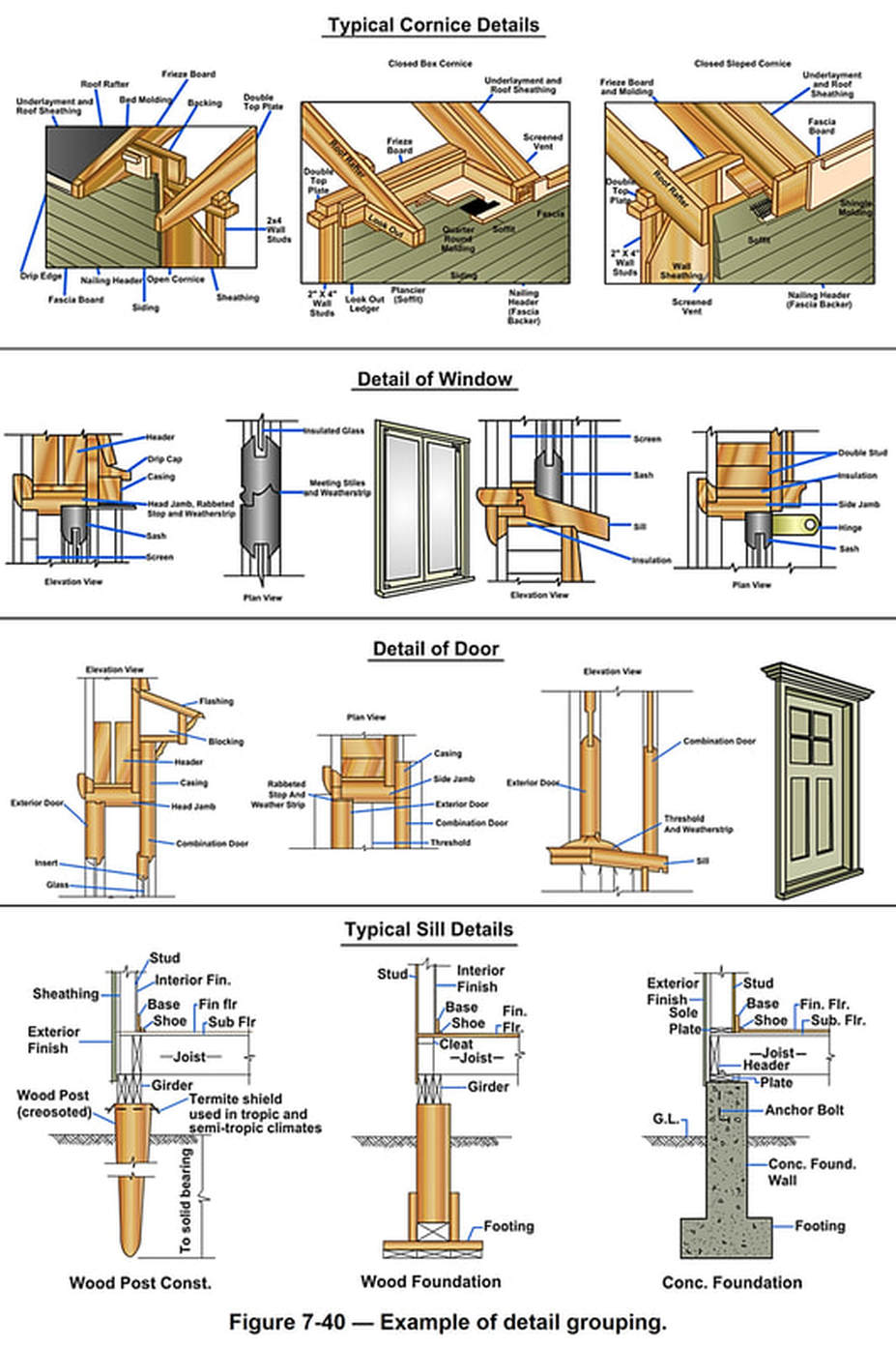
Details are commonly used for some specific phases and elements of construction such as foundations, doors, windows, cornices, and so forth (Figure 7-40). Show their details with the applicable main division of construction drawings and group them so that references can be made easily from the general drawing.
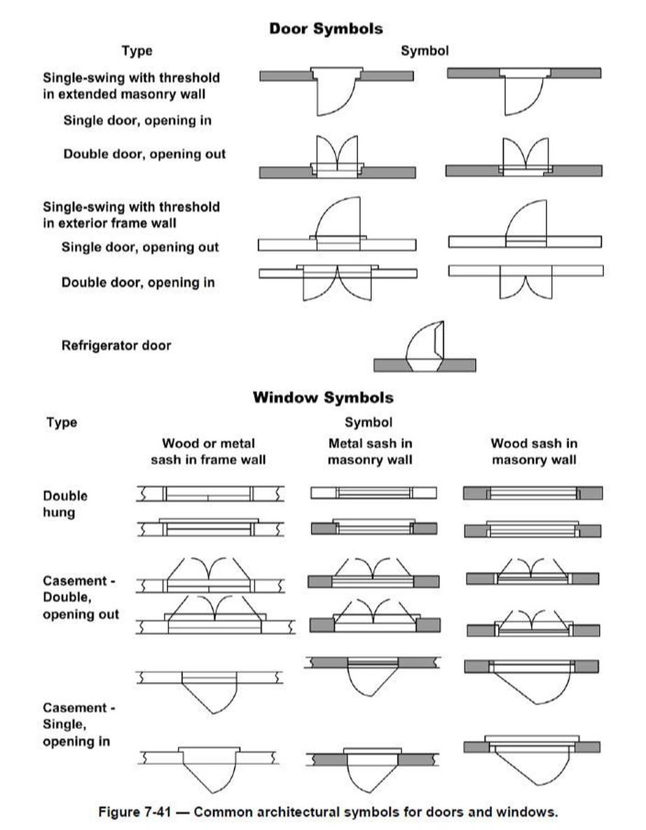
Use architectural symbols (Figure 7-41) to provide reference locations for doors and windows in general, sectional, and detail drawings.
Architectural drawing standards contain details commonly used for installation of items such as door-frames, window frames, fireproofing, and material connections; they do, however, need to be adapted to the particular building being drawn. When different conditions actually exist, avoid the use of “typical” details; they will be misleading and cause confusion. The designer needs to understand construction well enough to make accurate detail drawings for each unique situation.
Details are commonly used for some specific phases and elements of construction such as foundations, doors, windows, cornices, and so forth (Figure 7-40). Show their details with the applicable main division of construction drawings and group them so that references can be made easily from the general drawing.
Use architectural symbols (Figure 7-41) to provide reference locations for doors and windows in general, sectional, and detail drawings.