COMMON TERMINOLOGY AND SYMBOLS
In learning to read machine drawings, you must first become familiar with the common terms, symbols, and conventions defined and discussed in the following paragraphs.
General Terminology
The following paragraphs cover the common terms most used in all aspects of machine drawings.
Tolerances
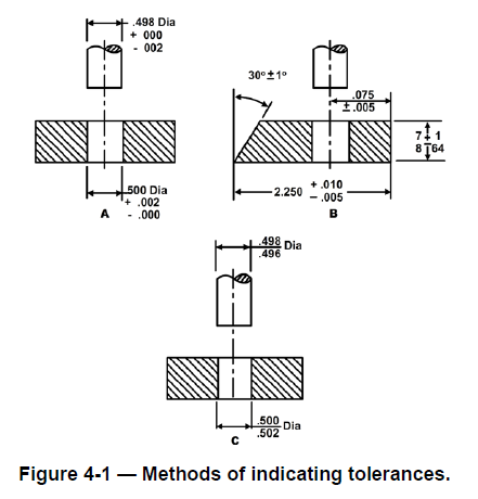
Engineers realize that absolute accuracy is impossible, so they calculate how much variation is permissible. This variation is known as tolerance. It is stated on a drawing as plus (+) or minus (-) a certain amount, either by a fraction or decimal. Limits are the maximum and/or minimum values prescribed for a specific dimension, while tolerance represents the total amount by which a specific dimension may vary. Tolerances may be shown on drawings by several different methods; Figure 4-1 shows three examples. The unilateral method (view A) is used when variation from the design size is permissible in one direction only. In the bilateral method (view B), the dimension figure shows the plus or minus variation that is acceptable. In the limit dimensioning method (view C), the maximum and minimum measurements are both stated.
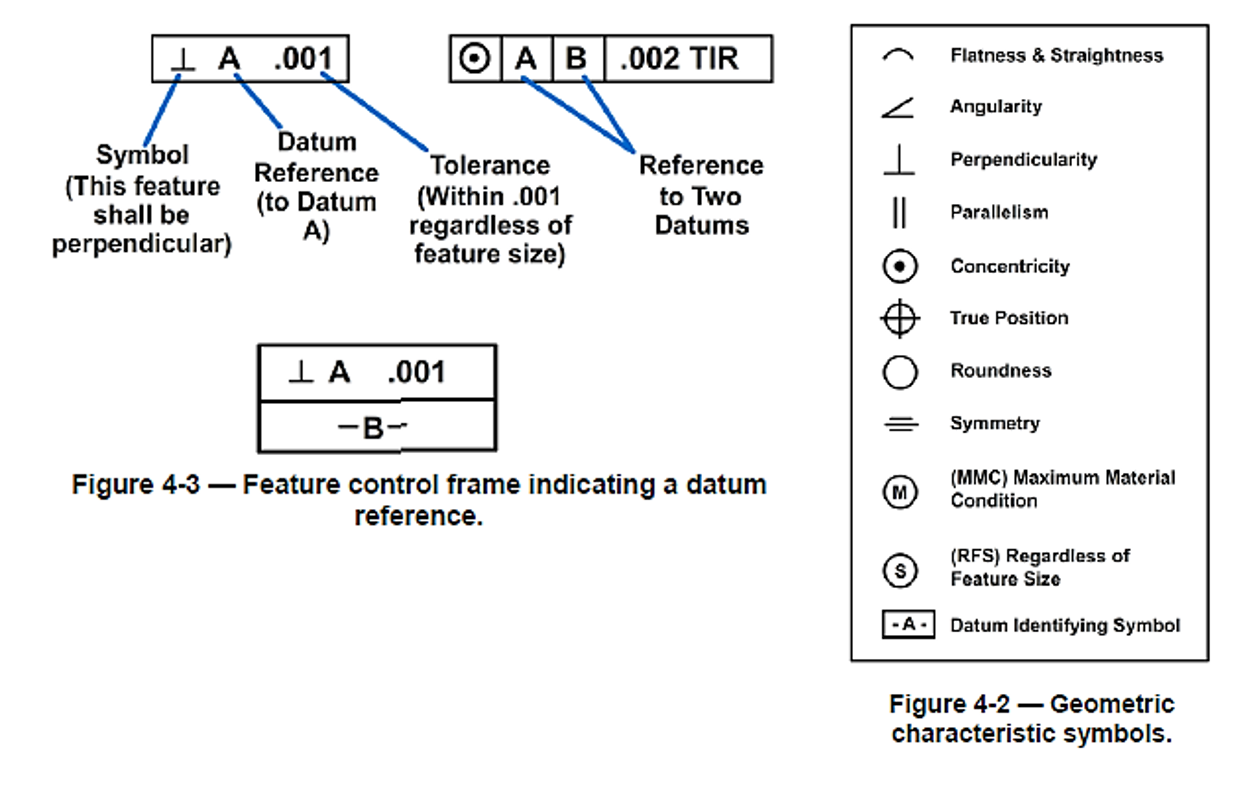
The surfaces being toleranced have geometrical characteristics such as roundness, or perpendicularity to another surface. Typical geometrical characteristic symbols are illustrated in Figure 4-2. A datum is a surface, line, or point from which a geometric position is to be determined or from which a distance is to be measured. Any letter of the alphabet except I, O, and Q may be used as a datum identifying symbol. A feature control symbol is made of geometric symbols and tolerances. A feature control symbol may include datum references (Figure 4-3).
Fillets and Rounds
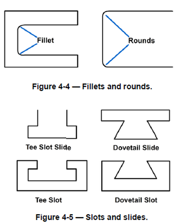
Fillets are concave metal corner (inside) surfaces. In a cast, a fillet normally increases the strength of a metal corner because a rounded corner cools more evenly than a sharp corner, thereby reducing the possibility of a break. Rounds or radii are edges or outside corners that have been rounded to prevent chipping and to avoid sharp cutting edges. Fillets and rounds are illustrated in Figure 4-4.
Slots and Slides
Slots and slides are used to mate two specially shaped pieces of material and securely hold them together, yet allow them to move or slide. The two types, the tee slot and the dovetail slot, are shown in Figure 4-5. For example, a tee slot arrangement is used on a milling machine table, and a dovetail is used on the cross slide assembly of an engine lathe.
Keys, Keyseats, and Keyways
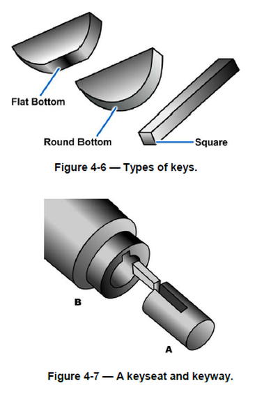
A key is a small wedge or rectangular piece of metal inserted in a slot or groove between a shaft and a hub to prevent slippage. Figure 4-6 shows three types of keys.
Figure 4-7 shows a keyseat and keyway. A keyseat (view A) is a slot or groove on the outside of a part into which the key fits. A keyway (view B) is a slot or groove within a cylinder, tube, or pipe. A key fitted into a keyseat will slide into the keyway and prevent movement of the parts.
SCREW THREADS
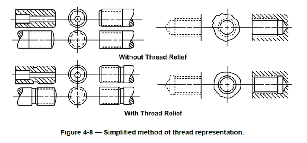
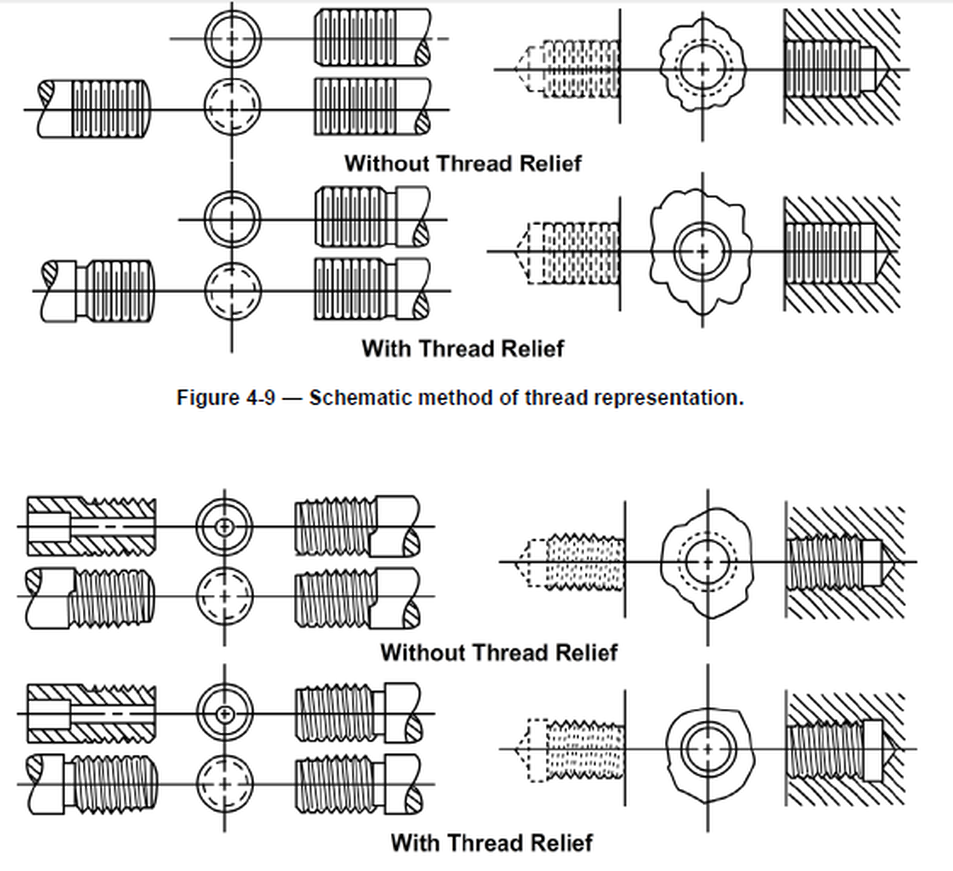
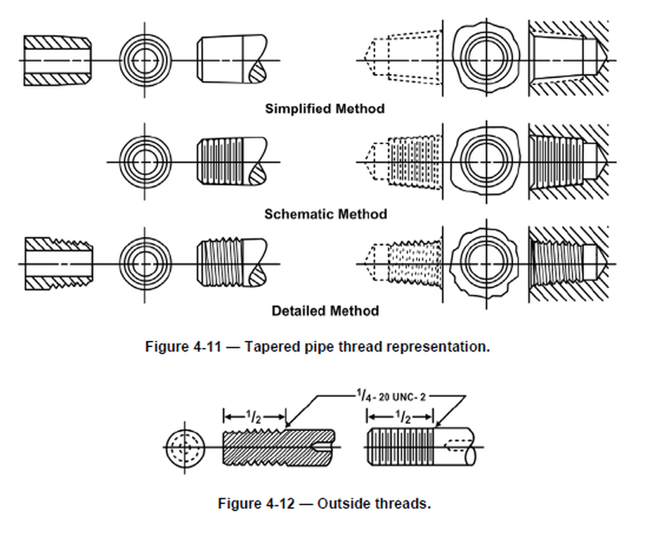
Different methods are used to show threads on drawings. The simplified method (Figure 4-8) uses visible and hidden lines to represent major and minor diameters of screw threads. The schematic method (Figure 4-9) uses staggered lines to represent the roots and crests of visible screw threads. The detailed method (Figure 4-10) provides the closest representation of the appearance of the actual screw thread. The simplified, schematic, and detailed method of thread representation used for tapered pipe threads is shown in Figure 4-11.
In Figure 4-12, the left side shows a thread profile in section and the right side shows a common method of drawing threads. To save time in a section view, symbols are used and the threads are not drawn to scale. The drawing shows the dimensions of the threaded part but other information may be placed in “notes” almost any place on the drawing but most often in the upper left corner.
However, in this example the note is directly above the drawing and shows the thread designator: 1/4-20 UNC-2. The first number of the note, 1/4, is the nominal size, which is the outside diameter. The number after the first dash, 20, means there are 20 threads per inch. The Unified National Coarse thread series is identified by the letters UNC. The last number, 2, identifies the class of thread and tolerance, commonly called the fit. If it is a left-hand thread, a dash and the letters LH will follow the class of thread. Threads without the LH are right-hand threads.
Specifications necessary for the manufacture of screws include thread diameter, number of threads per inch, thread series, and class of thread. The two most widely used screw-thread series are National Coarse (NC) and National Fine (NF) threads, which are part of the Unified or National Form Threads system. The NF threads have more threads per inch of screw length than the NC.
Classes of threads are distinguished from each other by the amount of tolerance and/or allowance specified. Class of thread was previously called class of fit; both terms are interchangeable. The term, class of thread, was established by the National Bureau of Standards in the Screw-Thread Standards for Federal Services, Handbook H-28.
Screw Threads Terminology
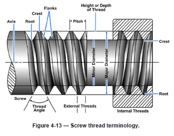
The terminology used to describe screw threads is illustrated in Figure 4-13. Each term is explained in the following paragraphs.
Axis
The axis is the center line running lengthwise through a screw.
External Thread
These threads are on the outside of a cylinder, such as a bolt or screw.
Internal Thread
These threads are on the inside of an object, such as a nut.
Crest
The crest is located at the top edge of the thread. This area corresponds to the major diameter of an external thread and the minor diameter of an internal thread.
Root
The root is the area at the bottom of the thread. This area of the thread corresponds to the minor diameter of an external thread and the major diameter of an internal thread.
Flank
The flank is the flat surface of the screw thread between the root and crest.
Major Diameter
This diameter is the largest measurement of an external or internal thread. The external thread major diameter is the outside measurement of the crest. The internal thread major diameter is the largest measurement of the root.
Minor Diameter
This diameter is the smallest measurement of an external or internal thread. The external thread minor diameter is the measurement of the root. The internal thread minor diameter is the measurement of the crest.
Pitch
The distance from a point on a screw thread to a corresponding point on the next thread, measured parallel to the axis.

Lead
The distance a screw thread advances on one turn, measured parallel to the axis. On a single-thread screw the lead and the pitch are identical; on a double-thread screw the lead is twice the pitch; on a triple-thread screw the lead is three times the pitch.
Helix
The curve formed on any cylinder by a straight line in a plane that is wrapped around the cylinder with a forward progression.
Depth
The distance from the root of a thread to the crest, measured perpendicularly to the axis.
GEARS
When sketching a gear on a machine drawing, usually only enough teeth are drawn to identify the necessary dimensions.
Gear Terminology
The terminology used to describe gears is illustrated in Figure 4-14. Each term is explained in the following paragraphs.
Pitch Diameter (PD)
The PD of a gear is equal to the number of teeth on the gear divided by the diametral pitch (DP).
Diametral Pitch (DP)
The DP is the ratio of the number of teeth per inch of the PD or the number of teeth on the gear divided by the PD. The DP is usually referred to as pitch.
Number of Teeth (N)
Multiply the DP by the PD (DP x PD) to find the number of teeth.
Pitch Circle
Pitch circle is an imaginary circle on a gear that divides the teeth into top and bottom lands (addendums and dedendums).
Addendum
Addendum is the height of the tooth above the pitch circle to the top of the tooth.
Dedendum
Dedendum is the length of the portion of the tooth from the pitch circle to the base of the tooth.
Addendum Circle (AC)
The AC is an imaginary circle over the tops of the gear teeth.
Outside Diameter (OD)
The OD is the diameter of the AC that contains the tops of the teeth.
Circular Pitch (CP)
The distance between the centers of two adjacent teeth, measured along the pitch circle.
Chordal Pitch
The distance from center to center of teeth measured along a straight line or chord of the pitch circle.
Root Diameter
The diameter of the circle measured at the root of the teeth.
Clearance
Clearance is the margin of space between the top of the tooth on one gear and the bottom of the tooth of the mating gear.
Whole Depth
The whole depth is the total distance from the top of the tooth to the bottom including the clearance.
Working Depth
The working depth is the greatest depth to which a tooth of one gear extends into the tooth space of another gear.
Face
The face of the tooth is the working surface of the tooth above the pitch line.
Thickness
The thickness of the tooth is the width of the tooth, taken as a chord of the pitch circle.
Rack Teeth
The toothed cuts made in a linear or rack gear, which, when meshed with a circular gear or pinion, change circular motion into
HELICAL SPRINGS
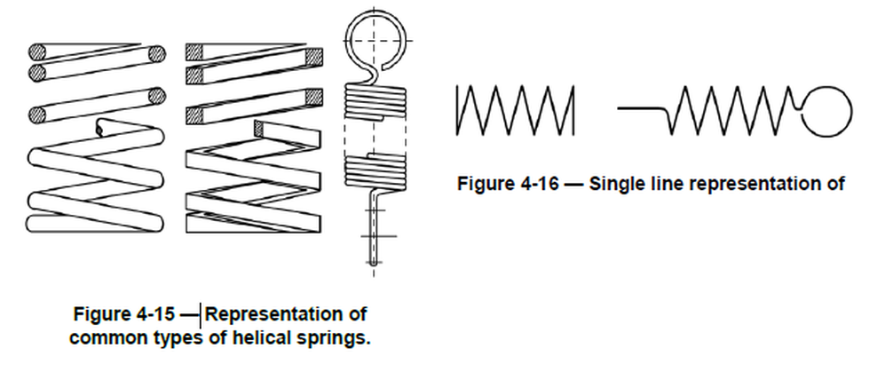
There are three classifications of helical springs: compression, extension, and torsion. Drawings seldom show a true representation of the helical shape; instead, they usually show springs with straight lines. Several methods of spring representation including both helical and straight-line drawings are illustrated in Figure 4-15. Also, springs are sometimes shown as single-line drawings, as in Figure 4-16.
FINISH MARKS
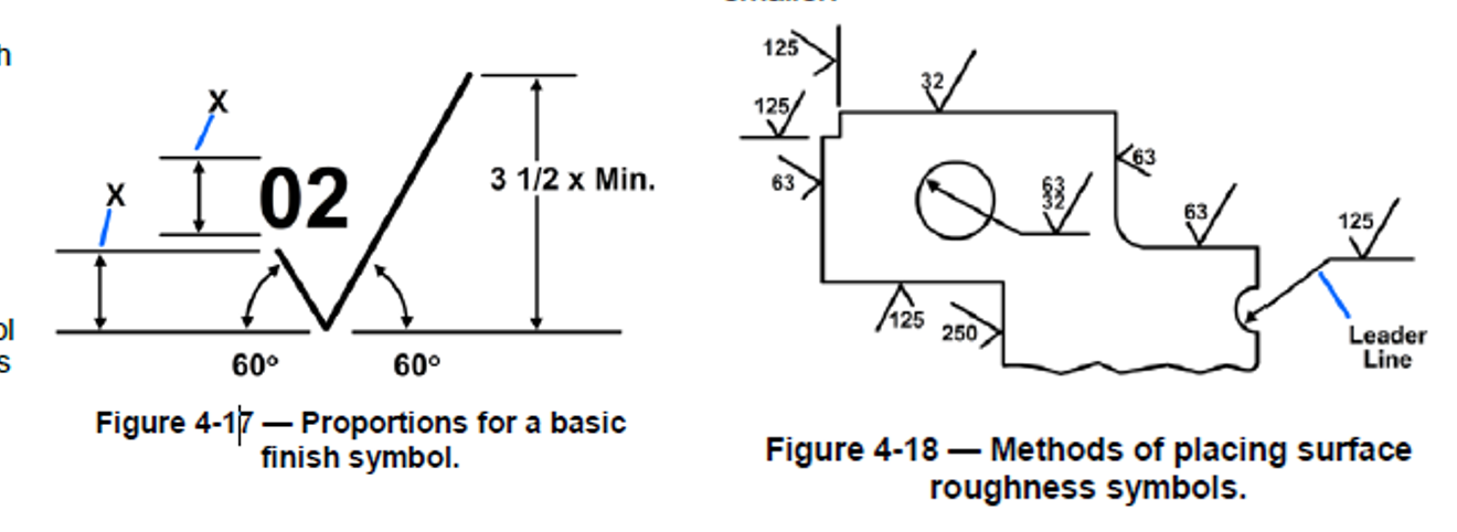
The military standards for finish marks are set forth in American Society of Mechanical Engineers (ASME) B46.1-2009, Surface Texture (Surface Roughness, Waviness, and Lay). Many metal surfaces must be finished with machine tools for various reasons. The acceptable roughness of a surface depends upon how the part will be used. Sometimes only certain surfaces of a part need to be finished while others are not. A modified symbol (check mark) with a number or numbers above it is used to show these surfaces and to specify the degree of finish. The proportions of the surface roughness symbol are shown in Figure 4-17. On small drawings the symbol is proportionately smaller.
The number in the angle of the check mark, in this case 02, tells the machinist what degree of finish the surface should have. This number is the root-mean-square value of the surface roughness height in millionths of an inch. In other words, it is a measurement of the depth of the scratches made by the machining or abrading process.
Wherever possible, the surface roughness symbol is drawn touching the line representing the surface to which it refers. If space is limited, the symbol may be placed on an extension line on that surface or on the tail of a leader with an arrow touching that surface, as shown in Figure 4-18.
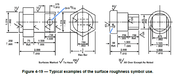
When a part is to be finished to the same roughness all over, a note on the drawing will include the direction “finish all over” along the finish mark and the proper number. An example is FINISH ALL OVER 32. When a part is to be finished all over but a few surfaces vary in roughness, the surface roughness symbol number or numbers are applied to the lines representing these surfaces and a note on the drawing will include the surface roughness symbol for the rest of the surfaces. For example, ALL OVER EXCEPT AS NOTED (Figure 4-19).
STANDARDS
American industry has adopted the standard, American National Standards Institute (ANSI) Y14.5M- 2009, Dimensioning and Tolerancing. This standard is used in all blueprint production, whether the print is drawn by a human hand or by computer-aided drawing (CAD) equipment. It standardizes the production of prints from the simplest hand-made job on site to single or multiple-run items produced in a machine shop with computer-aided manufacturing (CAM). For further information, refer to ANSI Y14.5M-2009 and to Introduction to Geometrical Dimensioning and Tolerancing, Lowell W. Foster, National Tooling and Machining Association, Fort Washington, MD, 1986.
The standards listed in Table 4-1 contain most of the information on symbols, conventions, tolerances, and abbreviations used in shop or working drawings:
Table 4-1 — Common Standards
Number Title
ANSI Y14.5M-2009 Dimensioning and Tolerancing
ANSI Y14.6-2001 Screw Thread Representation
ASME B46.1-2009 Surface Texture (Surface Roughness, Waviness, and Lay)
ASME Y14.38-2007 Abbreviations and Acronyms for Use on Drawings and Related Documents
Machine Drawing
Review Questions
A. Fillet
B. Major diameter
C. Minor diameter
D. Tolerance
4-2. In what dimensioning method are the minimum and maximum measurements stated?
A. Bilateral
B. Limit
C. Metric fillet
D. Unilateral
4-3. Which of the following terms describes a surface, line, or point from which a geometric position is to be determined?
A. Datum
B. Slot
C. Switch
D. Tatum
4-4. In a cast, what feature increases the strength of a metal corner?
A. Fillet
B. Keyseat
C. Slide
D. Slot
4-5. What feature describes a slot or groove on the outside of a part into which the key fits?
A. Fillets
B. Slots and slides
C. Key
D. Keyseat
4-6. What part of a thread designator number identifies the nominal or outside diameter of a thread?
A. The first
B. The second
C. The fourth
D. The letter designator
4-7. Which of the following screw-thread series are the most widely used?
A. European Coarse and European Fine
B. European Coarse and National Standard
C. National Coarse and National Fine
D. National Metric and National Standard
4-8. Which of the following terms distinguishes threads from each other by the amount of tolerance and/or allowance specified?
A. Class of pitch
B. Class of thread
C. National Standard
D. Thread pitch
4-9. Which of the following terms describes the surface of the thread that corresponds to the minor diameter of an external thread and the major diameter of an internal thread?
A. External threads
B. Axis
C. Crest
D. Root
4-10. Which of the following terms describes the largest measurement of the external or internal thread?
A. Crest
B. Major diameter
C. Minor diameter
D. Pitch
4-11. Which of the following definitions describes the term lead?
A. The distance a screw thread advances on one turn, parallel to the axis
B. The distance the thread is cut from the crest to its root
C. The distance from the thread's pitch to its root dimension
D. The distance between external threads
4-12. Which of the following terms defines the distance from the root of the thread to the crest, when measured perpendicularly to the axis?
A. Depth
B. Helix
C. Lead
D. Pitch
12
4-13. When sketching gears on a machine drawing, how many teeth are drawn?
A. One quarter
B. One half
C. Enough to identify the necessary dimensions
D. All
4-14. Which of the following terms expresses the number of teeth on the gear divided by the diametral pitch?
A. Pitch diameter
B. Outside diameter
C. Number of teeth
D. Addendum circle
4-15. Which of the following terms describes the imaginary circle that divided the teeth into top and bottom lands?
A. Addendum circle
B. Chordal pitch
C. Circular pitch
D. Pitch circle
4-16. Which of the following terms describes the imaginary circle over the tops of the teeth?
A. Addendum circle
B. Chordal pitch
C. Circular pitch
D. Pitch circle
4-17. Clearance is the marginal space between the top of one tooth and what other component?
A. Adjacent tooth
B. Gear axle
C. Bottom of the tooth on the mating gear
D. Top of the tooth on the mating gear
4-18. What term identifies the working surface of the tooth above the pitch line?
A. Addendum
B. Dedendum
C. Face
D. Thickness
4-19. What term describes the tooth cuts made in linear or rack gear?
A. Pitch circle
B. Working depth
C. Rack face
D. Rack teeth
4-20. Which of the following are the three classifications of helical springs?
A. Compression, extension, and double
B. Compression, extension, and torsion
C. Single, double, and triple
D. Single, extension, and torsion
4-21. What type of line is used to show springs on a drawing?
A. Broken
B. Curved
C. Spiral
D. Straight
4-22. What standard is used for finish marks?
A. ANSI 32.9-2006
B. ASME 14.3M
C. ASME B46.1-2009
D. IEEE 3009
4-23. Which of the following symbols is used to specify the degree of surface finish?
A. Check mark
B. Parenthesis
C. Rectangle
D. Triangle
4-24. On a finish symbol, the number indicates the degree of finish to what surface height, in inches?
A. Tenths
B. Hundredths
C. Thousandths
D. Millionths
4-25. What standard has the American industry adopted for blueprint production?
A.
B.
C.
D. IEEE 3009 ANSI 32.9-2006 ANSI Y14.5M-2009 ASME 14.3M
