STRUCTURAL SHAPES AND MEMBERS
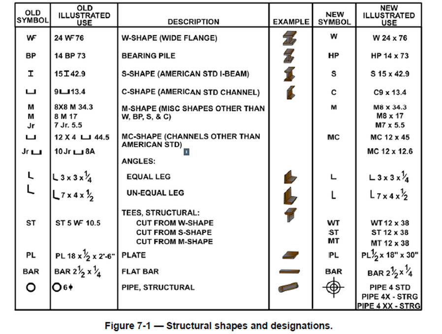
Various structural members are used to manufacture a wide variety of cross section shapes and sizes. Many of the shapes are shown in Figure 7-1. These symbols are compiled from part 4 of Military Standard 18B (MIL-STD-18B) and information from the American Society of Construction Engineers (ASCE). The following paragraphs will explain the common structural shapes used in building materials and the common structural members that are made in those shapes.
Shapes
The three most common types of structural members are the W-shape (wide flange), the S-shape (American Standard I-beam), and the C-shape (American Standard channel). These three types are identified by the nominal depth, in inches, along the web and the weight per foot of length, in pounds. As an example, a W 12 x 27 indicates a W-shape (wide flange) with a web 12 inches deep and a weight of 27 pounds per linear foot.
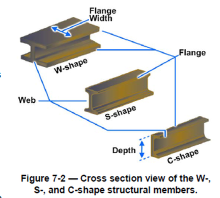
The cross-sectional views of the W-, S-, and C-shapes are illustrated in Figure 7-2. The difference between the W-shape and the S-shape is in the design of the inner surfaces of the flange. The W-shape has parallel inner and outer flange surfaces with a constant thickness, while the S-shape has a slope of approximately 17 degrees on the inner flange surfaces. The C-shape is similar to the S-shape in that its inner flange surface is also sloped approximately 17 degrees.
W-Shape
The W shape is a structural member whose cross section forms the letter H and is the most widely used structural member. It is designed so that its flanges provide strength in a horizontal plane, while the web gives strength in a vertical plane. W-shapes are used as beams, columns, and truss members, and in other load-bearing applications.
Bearing Pile
The bearing pile (HP-shape) is almost identical to the W-shape. The only difference is that the flange thickness and web thickness of the bearing pile are equal, whereas the W-shape has different web and flange thicknesses.
S-Shape
The S-shape (American Standard I-beam) is distinguished by its cross section being shaped like the letter I. S-shapes are used less frequently than W-shapes since the S-shapes possess less strength and are less adaptable than W-shapes.
C-Shape
The C-shape (American Standard channel) has a cross section somewhat similar to the letter C. It is especially useful in locations where a single flat face without outstanding flanges on one side is required. The C-shape is not very efficient for a beam or column when used alone. However, efficient built-up members may be constructed of channels assembled together with other structural shapes and connected by rivets or welds.
Channels
A cross section of a channel is similar to the squared letter C. Channels are identified by their nominal depth and weight per foot. For example, the American Standard channel notation C9 x 13.4 in Figure 7-1 shows a nominal depth of 9 inches and a weight of 13.4 pounds per linear foot, Channels are principally used in locations where a single flat face without outstanding flanges on a side is required. However, the channel is not very efficient as a beam or column when used alone. But the channels may be assembled together with other structural shapes and connected by rivets or welds to form efficient built-up members.
Angles
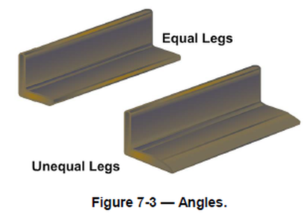
An angle (Figure 7-3) is a structural shape whose cross section resembles the letter L. Two types are commonly used: an equal-leg angle and an unequal-leg angle. The angle is identified by the dimension and thickness of its legs, for example, angle 6 inches by 4 inches by 1/2 inch. The dimension of the legs should be obtained by measuring along the outside of the backs of the legs. When an angle has unequal legs, the dimension of the wider leg is given first, as in the Figure 7-3 — Angles. example just cited. The third dimension applies to the thickness of the legs, which always have equal thickness. Angles may be used in combinations of two or four to form main members. A single angle may also be used to connect main parts together.
Plates
Generally, a main point to remember about plate is that it has a width of greater than 8 inches and a thickness of 1/4 inch or greater. Plates are generally used as connections between other structural members or as component parts of built-up structural members. Plates cut to specific sizes may be obtained in widths ranging from 8 inches to 120 inches or more, and in various thicknesses. The edges of these plates may be cut by shears (sheared plates) or be rolled square (universal mill plates).
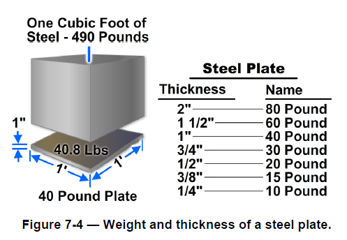
Frequently, plates are referred to by their thickness and width in inches, as plate 1/2 inch x 24 inches. The length in all cases is given in inches. Notice in Figure 7-4 that 1 cubic foot of steel weighs 490 pounds. This weight divided by 12 equaling 40.8, which is the weight (in pounds) of a steel plate 1 foot square and 1-inch thick. The fractional portion is normally dropped and 1-inch plate is called a 40-pound plate. In practice, you may hear plate referred to by its approximate weight per square foot for a specified thickness. An example is 20-pound plate, which indicates a 1/2-inch plate.
The designations generally used for flat steel have been established by the American Iron and Steel Institute (AISI). Flat steel is designated as bar, strip, sheet, or plate, according to the thickness of the material, the width of the material, and (to some extent) the rolling process to which it was subjected.
Tees
A structural tee is made by slitting a standard I- or H- beam through the center of its web, thus forming two T-shapes from each beam. In dimensioning, the structural tee symbol is preceded by the letters ST. For example, the symbol ST 5 WF 10.5 means the tee has a nominal depth of 5 inches, a wide flange, and weighs 10.5 pounds per linear foot. A rolled tee is a manufactured shape. In dimensioning, the rolled tee symbol is preceded by the letter T. The dimension T 4 x 3 x 9.2 means the rolled T has a 4-inch flange, a nominal depth of 3 inches, and a weight of 9.2 pounds per linear foot.
Zee
These shapes are noted by depth, flange width, and weight per linear foot. Therefore, Z 6 x 3 1/2 x 15.7 means the zee is 6 inches in depth, has a 3 1/2-inch flange, and weighs 15.7 pounds per linear foot.
Flat Bar
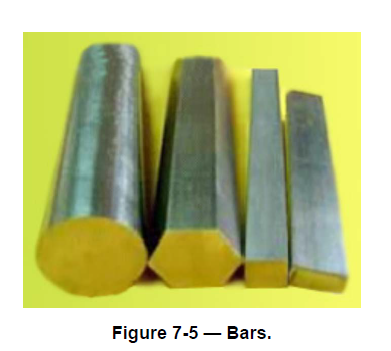
The structural shape referred to as bar has a width of 8 inches or less and a thickness greater than 3/16 of an inch. The edges of bars usually are rolled square, like universal mill plates. The dimensions are expressed in a similar manner as that for plates, for instance, bar 6 inches by 1/2 inch. Bars are available in a variety of cross-sectional shapes—round, hexagonal, octagonal, square, and flat. Four different shapes are illustrated in Figure 7-5. Both squares and rounds are commonly used as bracing members of light structures. Their dimensions, in inches, apply to the side of the square or the diameter of the round.
Columns
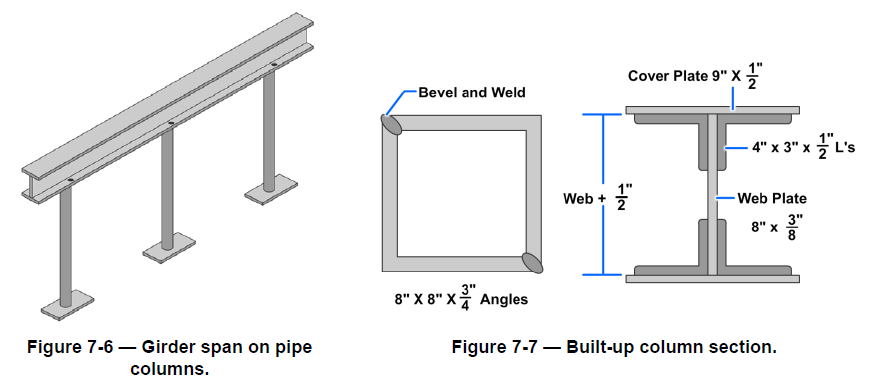
Typically, wide flange members, as nearly square in cross section as possible, are used for columns, but sometimes large diameter pipe is used, even though pipe columns can present connecting difficulties when you are attaching other members (Figure 7-6). Columns may also be fabricated by welding or bolting together a number of other rolled shapes, usually angles and plates (Figure 7-7).
Girders
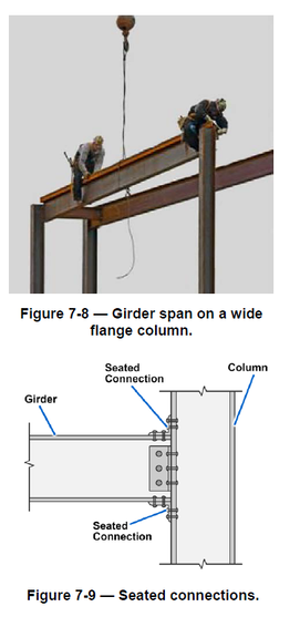
Girders are the primary horizontal members of a steel frame structure. They span from column to column and are usually connected on top of the columns with cap plates (bearing connections) (Figure 7-8). An alternate method is the seated connection (Figure 7-9). The girder is attached to the flange of the column using angles, with one leg extended along the girder flange and the other against the column. The function of the girders is to support the intermediate floor beams.
Members
The main parts of a structure are the load-bearing members. These support and transfer the loads on the structure while remaining equal to each other. The places where members are connected to other members are called joints. The total sum of the load supported by the structural members at a particular instant is equal to the total dead load plus the total live load.
The total dead load is the total weight of the structure, which gradually increases as the structure rises and remains constant once it is complete. The total live load is the total weight of movable objects, such as people, furniture, and bridge traffic, the structure happens to be supporting at a particular instant.
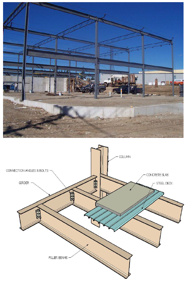
Basic System - Post & Beam (skeleton frame) and space frames.
2. Advantages of Steel Frame Construction:
1. Can build very tall and wide (tallest buildings in the world)
2. Light weight and strong (much lighter and stronger than concrete)
3. Prefabricated - frames assemble quickly
4. Precise and predictable (excellent quality control)
3. Disadvantages of Steel Frame Construction:
1. Steel is an expensive material (much more expensive than masonry or concrete)
2. Frames are unstable
3. Needs fire protection
4. Needs separate "skin" (walls and floors)
4. Methods of Stabilizing Steel Framed Buildings:
1. Rigid Core - Usually accomplished by interior masonry (or concrete) stair towers and elevator shafts that creates a vertical rigid core that resists deformation and torsion of the building due to external lateral forces.
2. Diagonal Bracing - The addition of diagonal "X" or "K" bracing that resists lateral loads. Problems - may interfere with exterior windows.
3. Moment-Resisting Beam-to-Column Connections - Typically accomplished by fabricating extra connection angles, welds and bolts that greatly increase the rigidity of the connection. Problems - extremely labor intensive and expensive.
4. Shear Walls - Exterior (or interior) walls built of masonry or concrete that act as a vertical cantilever beam resisting lateral loads. Problems - may interfere with exterior windows, labor intensive, heavy.
5. Basic Structural Steel Shapes (Hot-rolled):
In general, structural steel is fabricated in a hot-rolled process under several ASTM designations, the most common being A36. This steel has a minimum yield stress of 36 KSI and a minimum ultimate (breaking) stress of 58 KSI. Many other grades are available, with A572 - 50 KSI yield stress as a choice for higher strength. A new steel grade A992 has recently replaced A572 and A36 (for W sections) as the standard grade. Like A572, it also has a yield stress of 50 KSI.
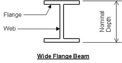
1. Wide Flange - The typical "I Beam" used in construction. Example - W18x35, where "W" = Wide flange, 18 = nominal depth of member in inches, and 35 = weight of beam in pounds per linear foot. Used for beams, columns, piles, bracing and other heavy applications.
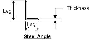
2. Angles - Either equal legs or unequal legs. Example - L4 x 3 x1/4 where 4 and 3 are the actual leg dimensions in inches and 1/4 = angle thickness in inches. Used for lintels, bracing, built-up beams and columns, secondary framing and other light-duty applications.
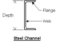
3. Steel Channels - These "C" shaped members are used for beams, built-up columns, bracing, secondary framing and other light to medium-duty applications. An example of a channel is C10x30 where "C" indicates channel, 10 is the actual height of the channel in inches, and 30 = pounds per linear foot.
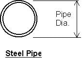
4. Steel Pipe - Circular pipe is used most often for columns. Comes in three categories based upon diameter and wall thickness, and are "standard weight", "extra strong" and "double extra strong". The double extra strong pipe is the strongest because it has the thickest walls. Example - Standard Weight 4" dia. pipe.
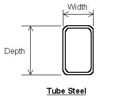
5. Tube Steel - These square or rectangular sections are used most often as columns, but may also be used as beams, bracing or other applications. A typical example is TS6x4x1/4 where TS = Tube Steel, 6 and 4 are the actual width and depth in inches, and 1/4 is the wall thickness in inches.
As of 2003, tube steel is now referred to as "Hollow Structural Section" (HSS) by the American Institute of Steel Construction. A typical designation is HSS6x4x1/4.
As of 2003, tube steel is now referred to as "Hollow Structural Section" (HSS) by the American Institute of Steel Construction. A typical designation is HSS6x4x1/4.
6. Plates - Flat pieces of steel cut to size. Generally in the range of 1/8" thick up to 6" thick. Used as column base plates, built-up beams and columns (i.e., plate girders), connection pieces (I.e., gusset plates, weld plates, etc.), and any other application where specific sized pieces are required. Example - PL 6x4x3/8 where 6 and 4 are length and width of the plate in inches and 3/8 is the plate thickness in inches.
7. Cut Sections - Typically these are wide flange sections that are cut in half to form a "T" section. Used for lintels, beams, bracing and columns. Example - WT7x19 is a section cut from a W14x38 wide flange.
7. Cut Sections - Typically these are wide flange sections that are cut in half to form a "T" section. Used for lintels, beams, bracing and columns. Example - WT7x19 is a section cut from a W14x38 wide flange.
5. Connections:
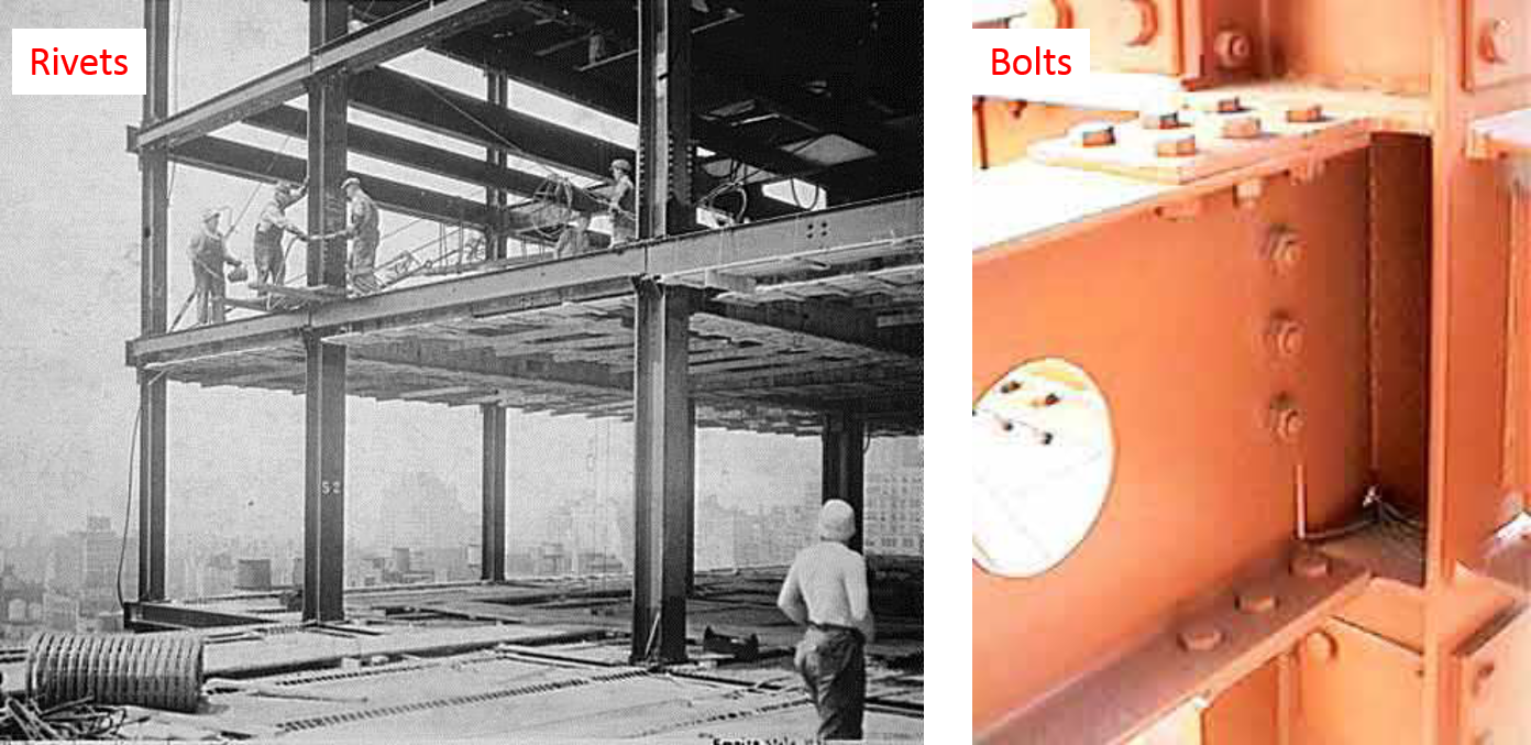
6. Rivets - Generally not used any more for reasons such as low strength, safety and poor quality control.
1. Bolts - Come in two varieties - carbon steel and high-strength. The carbon steel bolts obtain their strength through shear (or tension) along the shaft of the bolt only. The most common ASTM designation for carbon steel bolts used in structures is A307. These bolts cannot carry the same load that high-strength bolts can and are used for light-duty applications such as anchor bolts. High-strength bolts obtain their strength not only through the shear and tension along the shaft, but also from the friction forces that are generated from tensioning the nut to prescribed levels. The most common ASTM
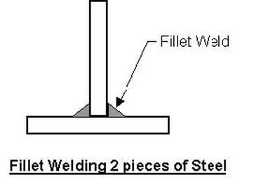
2. Welding - Welding is accomplished by mechanically joining steel together by heating electrodes into a molten state, which forms one piece from two. Creates extremely rigid connections. The most common type of weld used for building structures is the "fillet" weld, which joins pieces at right angles. It is common to shop-weld connection angles to beams and columns, then field-bolt them together at the job site.
7. Steel Decking:
Steel deck falls into one of several major types. All deck is cold-rolled and is sold in Gage thicknesses typically ranging from 16 (heaviest) to 28 Gage (lightest).
Steel deck falls into one of several major types. All deck is cold-rolled and is sold in Gage thicknesses typically ranging from 16 (heaviest) to 28 Gage (lightest).
1. Roof Deck - Generally available in heights of 1½" and 3" and gage thicknesses of 16 thru 22 gage. Roof deck is characterized by having a much wider top flute than bottom flute, for purposes of providing the largest possible flat surface for carrying non-structural building components such as rigid insulation. The bottom flute width varies, and different profiles are available such as "Narrow Rib", "Intermediate Rib" and "Wide Rib".
2. Floor Deck (Non-composite) - Used for floors, this type of deck has approximately equal length top and bottom flutes and acts as a form for concrete. Typical available heights are 9/16", 1", 1 5/16", 1½", 2" and 3". Concrete placed in the deck is generally reinforced with Welded Wire Fabric.
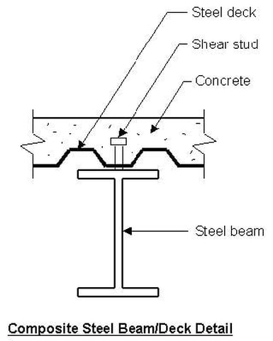
3. Floor Deck (Composite) - Similar to non-composite floor deck, this deck usually has additional perforations in the decking to "grip" the concrete. This deck acts as part of a structural system with steel beams. The deck is placed on top of the steel beam and steel "shear studs" are welded through the deck and onto the top flange of the beam. After the concrete is placed and cured, it grips the shear studs and acts compositely with the steel beam and greatly increases the load-carrying capacity of the steel beam alone.
8. Steel Joists (Bar Joists):
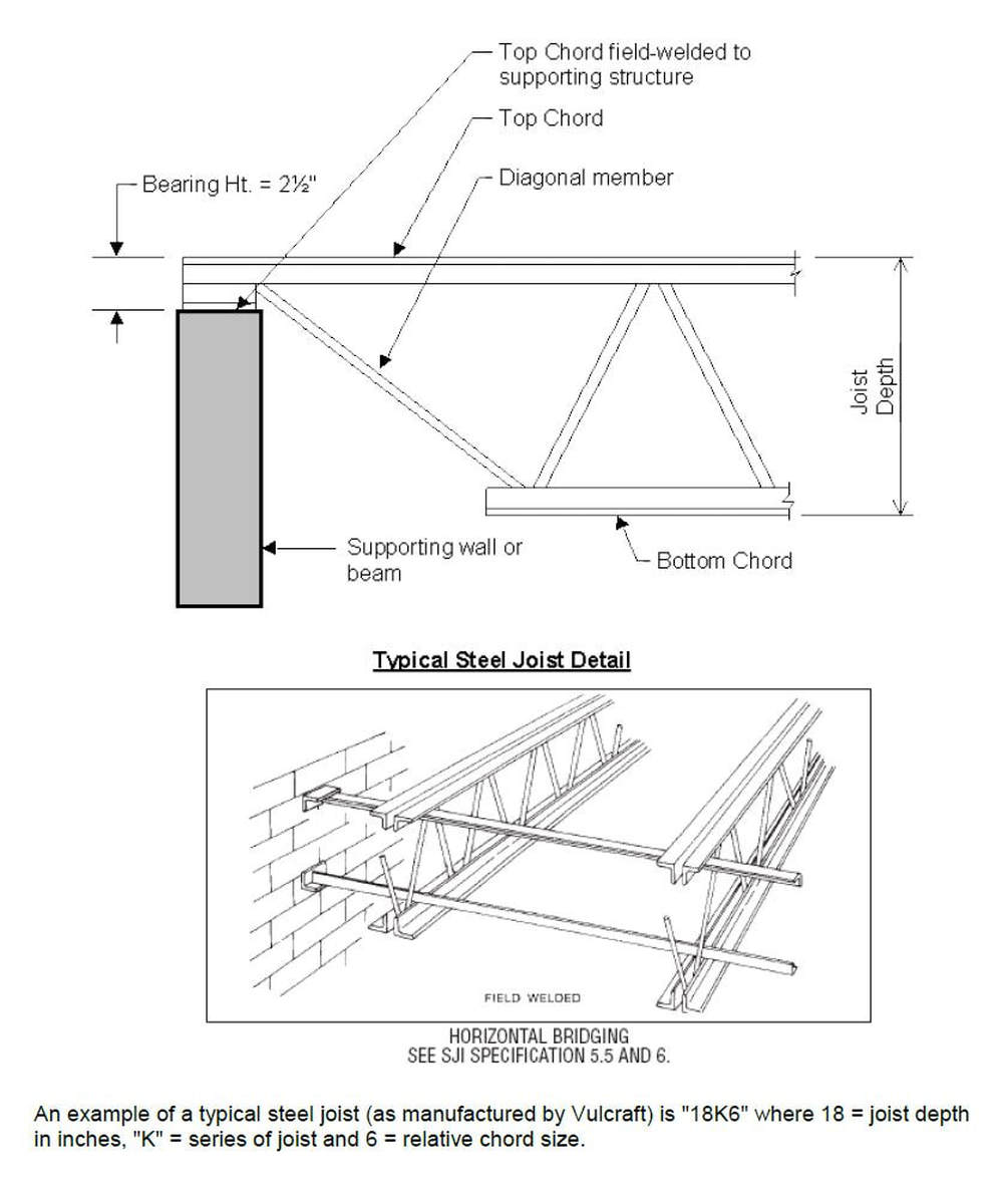
These lightweight, open-web "trusses" are manufactured by various companies (such as Vulcraft), to provide the lightest weight possible alternative to beams. They are used most often for roof assemblies. A typical steel joist is shown below:
These lightweight, open-web "trusses" are manufactured by various companies (such as Vulcraft), to provide the lightest weight possible alternative to beams. They are used most often for roof assemblies. A typical steel joist is shown below:
9. Light Gauge Steel Framing:
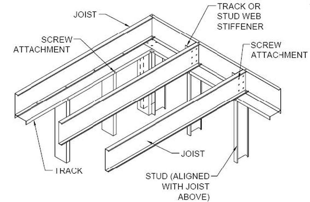
Light gauge steel framing members are used to frame walls, headers, joists, and lintels - everything that conventional wood-framing members would be used for. Most state building codes dictate that non-combustible construction be used for certain type facilities and wood framing members may NOT be used. These light gauge members are cold-rolled (similar to steel deck) sheet metal products that are available from various manufacturers in "C" shaped members in gages typically ranging from 12 gage up to 26 gage. They are fastened and assembled by use of self-tapping screws and spot-welding.
10. Fire Protection:
All steel structures must be fire protected as per state and local building codes. Although it takes a very substantial amount of heat to actually melt steel, it will lose most of its strength at temperatures above 7000 F. There are generally two major categories of fire proofing - thermal and absorptive.
1. Thermal Fire Protection - Slows heat passage through the steel. Methods used include providing insulation and in-tumescent paint.
2. Absorptive Fire Protection - Absorbs heat. Methods used include covering steel members with concrete, gypsum (spray-on), and elaborate methods such as liquid-filled chambers (generally wrapped around columns).
WELDED AND RIVETED STEEL STRUCTURES
The following paragraphs will discuss welded and riveted steel structures and will give examples of both methods used to make trusses.
Welded Steel Structures
Generally, welded connections are framed or seated just as they are in riveted connections, which we will discuss later. However, welded connections are more flexible. The holes used to bolt or pin pieces together during welding are usually drilled in the fabrication shop. Beams are not usually welded directly to columns. The procedure produces a rigid connection and results in severe bending that stresses the beam, which must be resisted by both the beam and the weld.
Welding Symbol
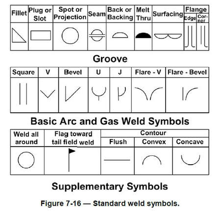
Drawings contain special symbols to specify the weld location, type of joint, and size and amount of weld metal to be deposited in the joint. The American Welding Society (AWS) has standardized them. A welder will see them whenever he or she performs a welding job from a set of prints, so you need to be familiar with all the elements of a standard welding symbol, and the location and meaning of the basic weld symbols.
A standard welding symbol (Figure 7-15) is: reference line + arrow + tail.
The reference line is the foundation. Weld symbols, dimensions, and other data are applied to it. The arrow connects the reference line to the joint or area to be welded. The direction of the arrow has no bearing on the significance of the reference line. The tail of the welding symbol is used only when necessary to include a process, specification, or other reference information.
Type of Weld Symbols
Weld symbols refer to the symbols for a specific type of weld, such as fillet, groove, butt, surfacing, plug, or slot.
The weld symbol (Figure 7-16) is only part of the information required in the welding symbol. When used to disseminate information, the term welding symbol refers to the total symbol, which includes all the weld symbols needed to specify the weld(s) required.
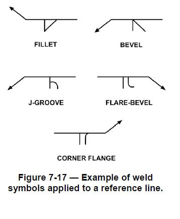
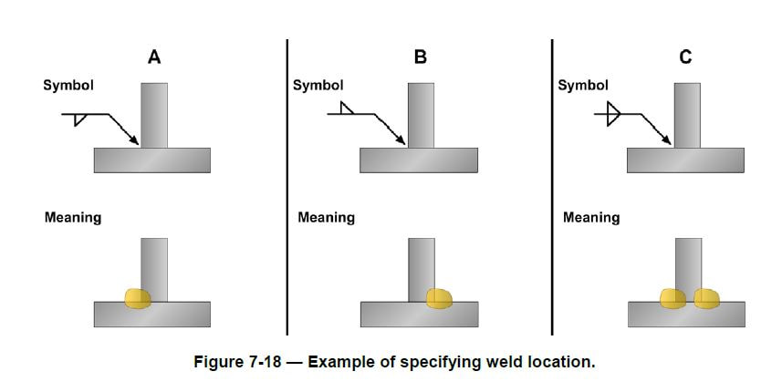
How the weld symbol is applied to the reference line is shown in Figure 7-17. Notice that the vertical leg of the weld symbol is shown drawn to the left of the slanted or curved leg of the symbol. Regardless of whether the symbol is for a fillet, bevel, J-groove, or flare-bevel weld, the vertical leg is always drawn to the left. The significance of the weld symbol’s position on the reference line is depicted in Figure 7-18.
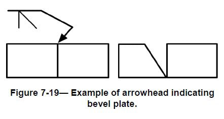
When only one edge of a joint is to be beveled, it is necessary to show which member is to be beveled (Figure 7-19). When such a joint is specified, the arrow of the welding symbol points with a definite break toward the member to be beveled. Other weld symbols may be added to a welding symbol as necessary to communicate all the information needed for the weld.
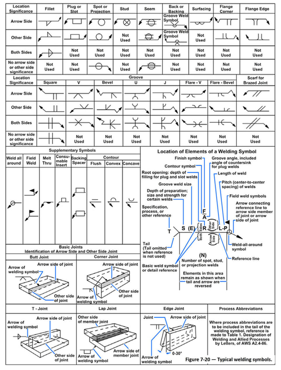
However, regardless of the direction of the arrow, all information applied to the reference line on a welding symbol is read from left to right. A listing of welding symbols is shown in Figure 7-20.
However, regardless of the direction of the arrow, all information applied to the reference line on a welding symbol is read from left to right. A listing of welding symbols is shown in Figure 7-20.
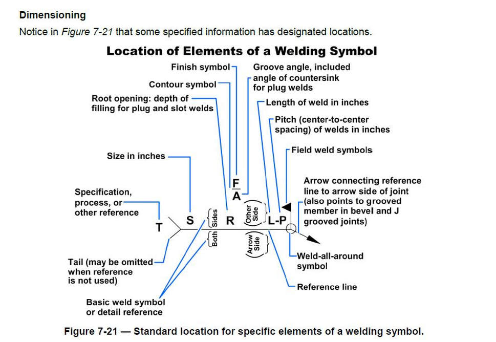
The size, length, pitch (center-to-center spacing), groove angle, and root opening of a weld all have designated locations. These locations are determined by the side of the reference line on which the weld symbol is placed.
Supplementary
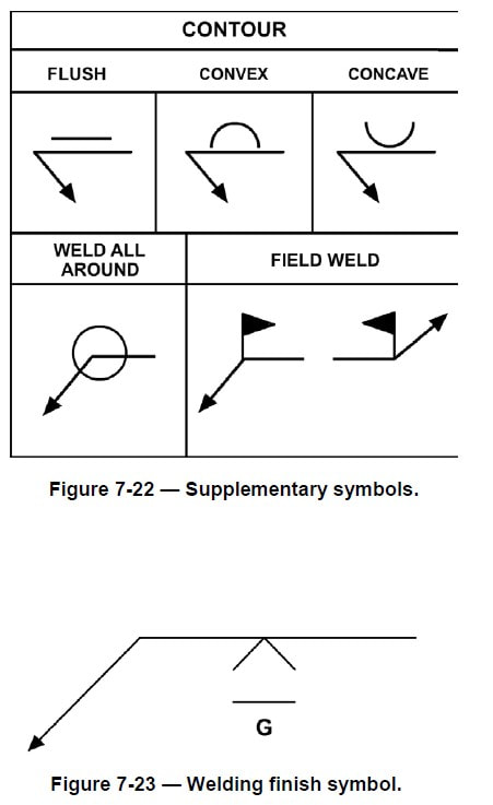
Besides the basic weld symbols, the welding symbol may include supplementary symbols (Figure 7-22). Contour symbols show how the face is to be formed; finish symbols indicate the method to use to form the contour.
A finish symbol (when used) shows the method of finish, C represents chipping, M means machining, and G indicates grinding, not the degree of finish. How contour and finish symbols are applied to a welding symbol is illustrated in Figure 7-23. This symbol indicates the weld is to be ground flush. Also, notice that the symbols are placed on the same side of the reference line as the weld symbol.
Another supplementary symbol is the weld-all-around symbol. When this symbol is placed on a welding symbol, welds are to continue all around the joint.
Yet another symbol on Figure 7-22 is the field weld symbol, a black flag that points toward the tail of the welding symbol. For welds that cannot be made in the shop, for size, transportation, constructability, or other reasons, this symbol directs the welder to make the weld in the field, which could be “in situ” or on site.
Welded Steel Trusses
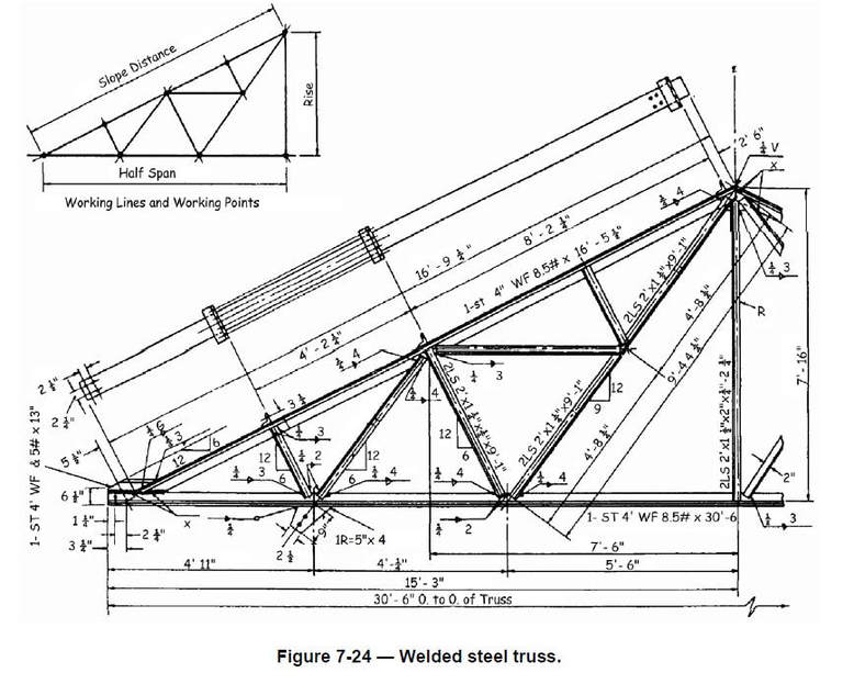
A drawing of a typical welded steel truss is illustrated in Figure 7-24. When you interpret the welding symbols, you will see that most of them show that the structural angles will be fillet welded. The fillet will have a 1/4 inch radius (thickness) on both sides and will run along the angle for 4 inches.
A drawing of a typical welded steel truss is illustrated in Figure 7-24. When you interpret the welding symbols, you will see that most of them show that the structural angles will be fillet welded. The fillet will have a 1/4 inch radius (thickness) on both sides and will run along the angle for 4 inches.
Riveted Steel Structures
Steel structural members are riveted in the shop where they are fabricated to the extent allowed by shipping conditions. During fabrication, all rivet holes are punched or drilled whether the rivets are to be driven in the field or in the shop.
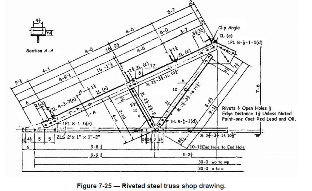
Look at the shop fabrication drawing of a riveted steel roof truss in Figure 7-25. At first look, it appears cluttered and hard to read. This is caused by the many dimensions and other pertinent facts required on the drawing, but you can read it once you understand what you are looking for, as we will explain in the next paragraphs.
The top chord is made up of two angles labeled with specification 2L 4 x 3 1/2 x 5/16 x 16´-5 1/2". This means the chord is 4 inches by 3 1/2 inches by 5/16 inch thick and 16 feet 5 1/2 inches long.
The top chord also has specification IL 4 x 3 x 3/8 x 7(e). This means it has five clip angles attached, and each of them is an angle 4 inches by 3 inches by 3/8 inch thick and 7 inches in length.
The gusset plate (a) on the lower left of the view is labeled PL 8 x 3/8 x 1´-5 (a). That means it is 8 inches at its widest point, 3/8 inch thick, 1 foot 5 inches long at its longest point.
The bottom chord is made up of two angles 2 1/2 inches by 2 inches by 5/16 inches by 10 feet 3 7/16 inches which are connected to gusset plates A and B, and two more angles 2 1/2 inches by 2 inches by 1/4 inches by 10 feet 4 1/8 inches which are connected to gusset plate B and continue to the other half of the truss. Two more angles are connected to gusset plates C and B on the top and bottom chords; they are 2 1/2 inches by 2 inches by 1/4 inches by 2 feet 10 1/2 inches. The other member between the top and bottom chords, connected to gusset plate B and the purlin gusset D, is made up of two angles 2 1/2 inches by 2 inches by 1/4 inches by 8 feet 5 inches.
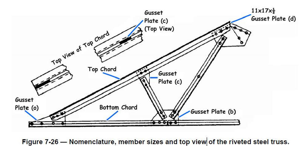
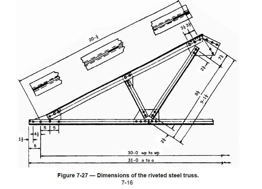
Figure 7-27 — Dimensions of the riveted steel truss.
In Figure 7-26, the same truss is shown with only the names of some members and the sizes of the gusset plates (A, C, and D) between the angles.
In Figure 7-27, the same truss is shown with only a few of the required dimensions to make it easier to read the complete structural shop drawing.
In Figure 7-26, the same truss is shown with only the names of some members and the sizes of the gusset plates (A, C, and D) between the angles.
In Figure 7-27, the same truss is shown with only a few of the required dimensions to make it easier to read the complete structural shop drawing.
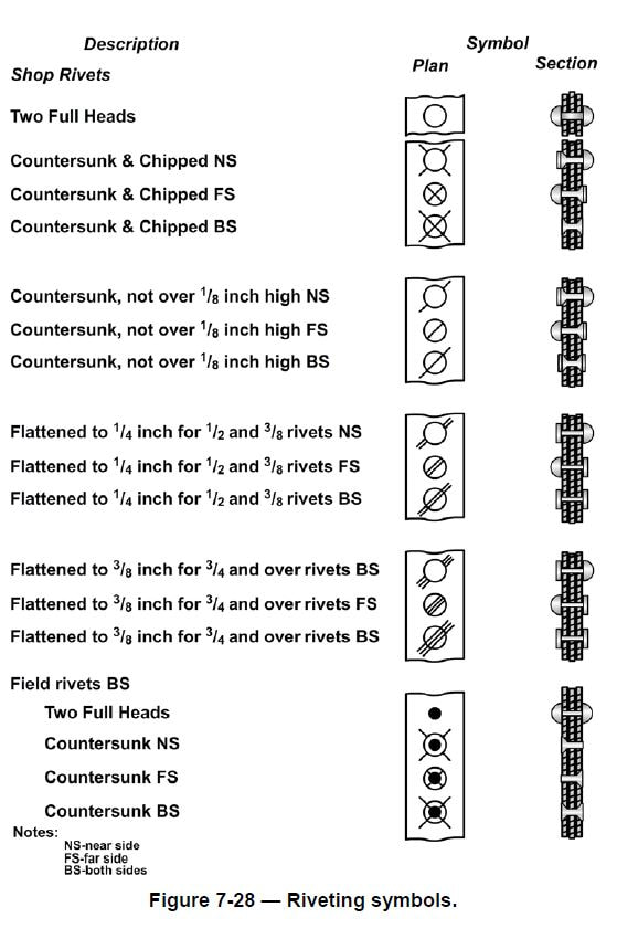
Most of the rivets will be driven in the shop with the exception of five rivets in the purlin gusset plate d and the two rivets shown connecting the center portion of the bottom chord, which is connected to gusset plate b. These seven rivets will be driven at the job site. Conventional symbols for rivets driven in the shop and in the field are shown in Figure 7-28.
DRAWINGS OF STEEL STRUCTURES
Blueprints used for the fabrication and erection of steel structures usually consist of a group of different types of drawings such as layout, general, fabrication, erection, and false work. These drawings are described in the following paragraphs.
Layout Drawings
Layout drawings are also called general plans and profile drawings. They provide the necessary information on the location, alignment, and elevation of the structure and its principal parts in relation to the ground at the site. They also provide other important details, such as the nature of the underlying soil or the location of adjacent structures and roads. These drawings are supplemented by instructions and information known as written specifications.
General Plans
General plans contain information on the size, material, and makeup of all main members of the structure, their relative position and method of connection, as well as the attachment of other parts of the structure. The number of general plan drawings supplied is determined by such factors as the size and nature of the structure, and the complexity of operations. General plans consist of plan views, elevations, and sections of the structure and its various parts. The amount of information required determines the number and location of sections and elevations.
Fabrication Drawings
Fabrication drawings, or shop drawings, contain necessary information on the size, shape, material, and provisions for connections and attachments for each member. This information is in enough detail to permit ordering the material for the member concerned and its fabrication in the shop or yard. Component parts of the members are shown in the fabrication drawing, as well as dimensions and assembly marks.
Erection Drawings
Erection drawings, or erection diagrams, show the location and position of the various members in the finished structure. They are especially useful to personnel performing the erection in the field. For instance, the erection drawings supply the approximate weight of heavy pieces, the number of pieces, and other helpful data.
False work Drawings
The term false work refers to temporary supports of timber or steel required in the erection of difficult or important structures. When false work is required on an elaborate scale, drawings similar to the general and detail drawings already described may be provided to guide construction. For simple false work, field sketches may be all that is needed.
