PIPING DRAWINGS
Water was at one time the only important fluid that was moved from one point to another in pipes. Today almost every conceivable fluid is handled in pipes during its production, processing, transportation, and use. The age of atomic energy and rocket power has added fluids such as liquid metals, oxygen, and nitrogen to the list of more common fluids such as oil, water, gases, and acids that are being carried in piping systems today. Piping is also used as a structural element in columns and handrails. For these reasons contractors, manufacturers, and engineers should become familiar with pipe drawings. Piping drawings show the size and location of pipes, fittings, and valves. A set of symbols has been developed to identify these features on drawings.
Two methods of projection used in pipe drawings are orthographic and isometric (pictorial). Orthographic projection is used to show multiple views of an object in a single plane. Isometric projection is used to show a three-dimensional view of an object in single plane.
Orthographic Pipe Drawings
Single- and double-line orthographic pipe drawings (Figures 5-1 and 5-2) are recommended for showing single pipes either straight or bent in one plane only. This method also may be used for more complicated piping systems.
Figure
Isometric (Pictorial) Pipe Drawings
Picture-based projection is used for all pipes bent in more than one plane, and for a device made up of smaller parts and layout work. The finished drawing is easier to understand in the picture-based format.
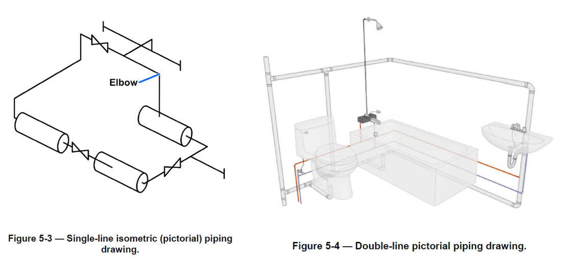
Single-line drawings show the arrangement of pipes and fittings. A single-line isometric picture-based drawing of Figure 5-1 is illustrated in Figure 5-3. The center line of the pipe is drawn as a thick line to which the valve symbols are added.
Single-line drawings take less time and show all information needed to lay out and produce a piping system.
Double-line pipe drawings require more time to draw and therefore are not recommended for production drawings. An example of a double-line pictorial pipe drawing is shown in Figure 5-4. They are generally used for catalogs and similar applications where visual appearance is more important than drawing time.
Connections
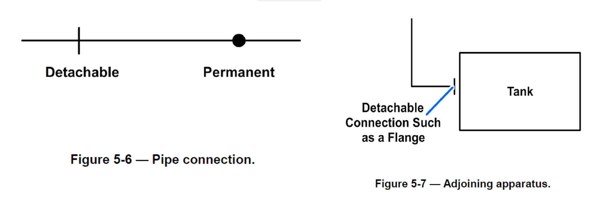
Permanent connections, whether made by welding or other processes such as gluing or soldering, should be shown on the drawing by a heavy dot (Figure 5-6). A general note or specification is used to describe the type of connection.
Detachable connections are shown by a single thick line (Figures 5-6 and 5-7). The specification, a general note, or bill of material will list the types of connections such as flanges, unions, or couplings and whether the fittings are flange or threaded.
Fittings
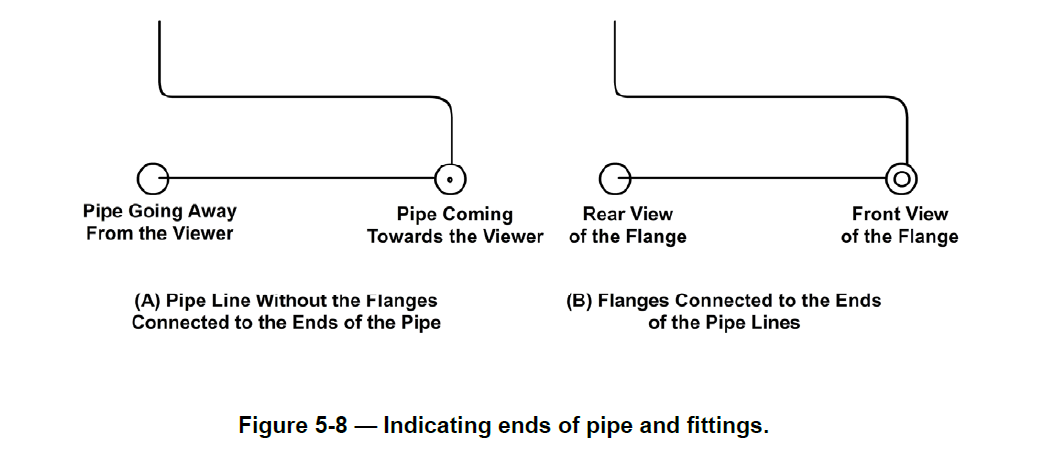
If standard symbols for fittings such as tees, elbows, and crossings are not shown on a drawing, they are represented by a continuous line. They define the size of the pipe, the method of branching and coupling, and the purpose of the pipe. This information is important because the purpose of the pipe determines what piping material to use. The inverse is also true; the piping material will determine how it can be used. A circular symbol for a tee or elbow may be used to indicate the piping coming toward or moving away from the viewer, as shown in Figure 5-8.
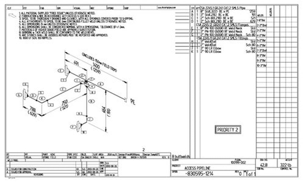
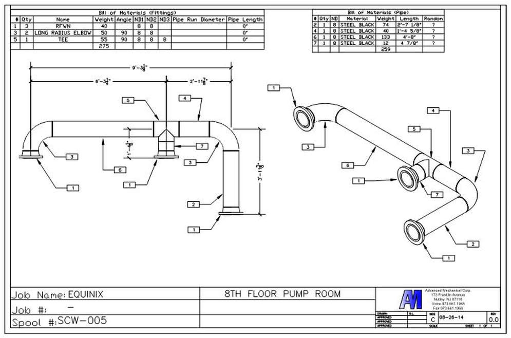
EXAMPLES OF PIPING DRAWINGS

